TorpedoAUV
Description
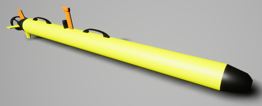
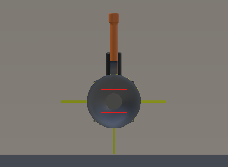
A generic torpedo-style AUV with four fins.
See the TorpedoAUV.
Control Schemes
- AUV Fins (``0``)
Takes in a 5 length vector of four fin angles and a thruster value. The format is [Right Fin, Top Fin, Left Fin, Bottom Fin, Thruster]. Fins have a range of -45 to 45 degrees, and the thruster has a range of -100 to 100 (percent of max thrust).
- Custom Dynamics (``1``)
A 6-length floating point vector of linear and angular accelerations in the global frame. This is to be used for implementing custom dynamics. Besides collisions, all other forces and torques (including gravity, buoyancy, and damping) have been disabled in the simulator to allow for a clean slate for custom dynamics.
Note
Dynamics models from Thor Fossen are available for the TorpedoAUV to enable more realistic simulations. To use Fossen dynamics, use the Custom Dynamics control scheme, then create a Fossen vehicle controller and a Fossen dynamics manager. For details, see Fossen-Based Dynamics.
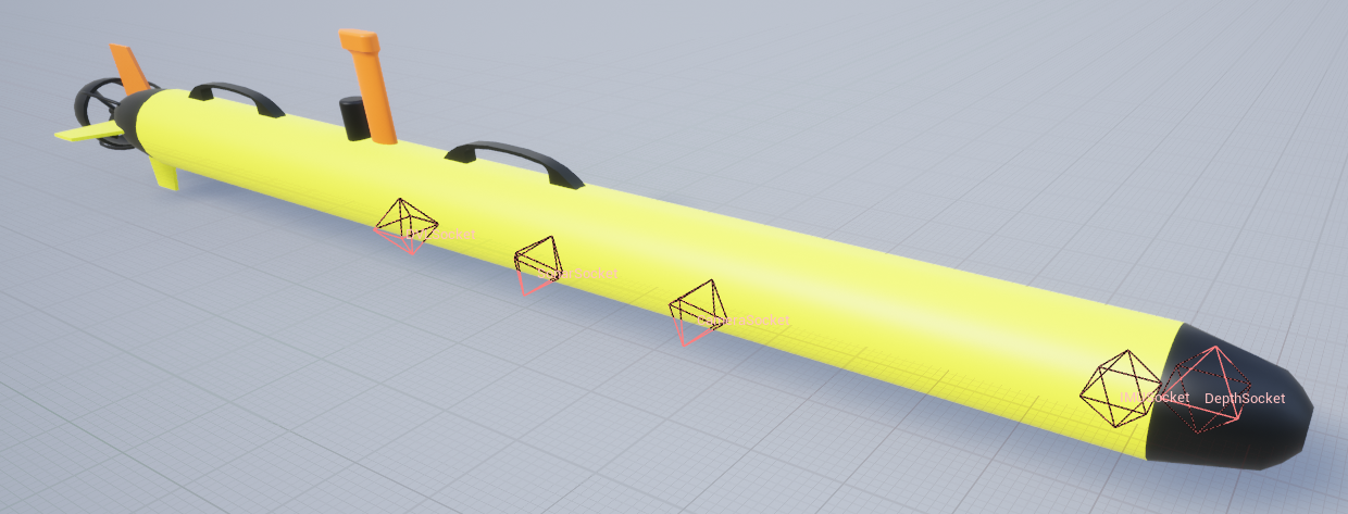
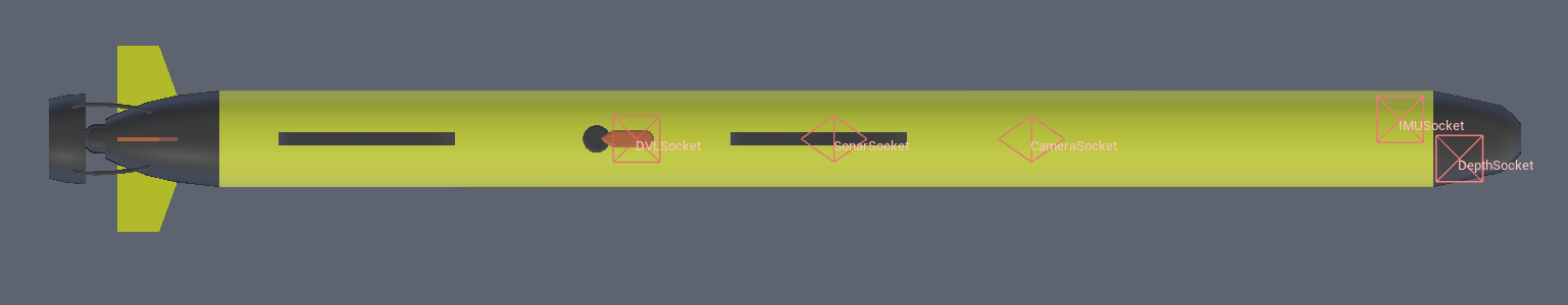
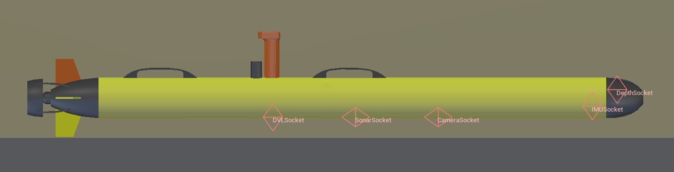
Sockets
All sockets have standard orientation unless stated otherwise. Standard orientation has the x-axis pointing towards the front of the vehicle, the y-axis pointing starboard, and the z-axis pointing upwards.
Socket Definitions
COMCenter of mass.CameraSocketLocation of camera, rotated -90 on y-axis.DVLSocketLocation of the DVLIMUSocketLocation of the IMU.DepthSocketLocation of the depth sensor.SonarSocketLocation of the sonar sensor, rotated -90 on y-axis.Viewportwhere the robot is viewed from.
Socket Frames
Flashlights
The TorpedoAUV comes with a single forward-facing flashlight mounted at the front of the vehicle for illumination.
flashlight1: (105, 0, 0)
Please refer to flashlights for information on available control commands.